Table of Contents
Anatomy of Mapleson Breathing Circuit
Basically, a mapleson breathing circuit consists of following parts:
1. Face mask (towards patient end)
2. Reservoir bag (towards operator end)
- Accommodates fresh gas flow during expiration acting as a reservoir available for the following inspiration.
- Acts as a monitor of patient’s ventilatory pattern during spontaneous breathing and also a very inaccurate guide to tidal volume.
- Used to assist or control ventilation.
3. Corrugated tube (between face mask and reservoir bag)
4. Fresh gas flow (FGF) inlet (at variable position)
5. Expiratory valve or Adjustable Pressure Limiting (APL) valve (at variable position)
- One-way, adjustable, spring-loaded valve.
- Valve allows gases to escape when the pressure in the breathing system exceeds the valve’s opening pressure.
- During spontaneous ventilation, the patient generates a positive pressure during expiration, causing the valve to open.
- During positive pressure ventilation, a controlled leak is produced in inspiration by adjusting the valve dial, allowing control of the patient’s airway pressure.
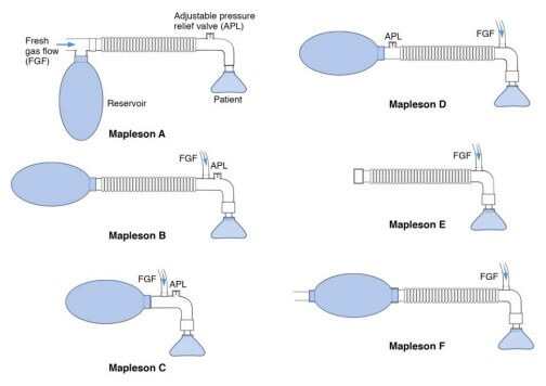
Identification of Different types of Mapleson circuit
Mapleson A (Magill’s System)
- FGF inlet is near reservoir bag.
- APL valve is near face mask.
Lack’s system: Co-axial modification of Mapleson A with APL valve away from patient end, i.e. face mask.
Mapleson B and C
- FGF inlet and APL valve are close to face mask (FGF inlet being just distal to APL valve).
- Mapleson B has a corrugated tube, while the Mapleson C (Water’s circuit without an absorber) doesn’t have a corrugated tube.
Mapleson D
- FGF inlet is close to patient’s face mask.
- APL valve is placed just before the reservoir bag, i.e. FGF inlet is proximal to APL valve.
Bain’s system: Co-axial modification of Mapleson D in which the FGF supply runs inside the corrugated tube through which the expired gases are eliminated.
Mapleson E (Ayre’s T piece)
- FGF inlet is close to face mask.
- No APL valve and reservoir bag.
Mapleson F (Jackson Ree’s Modification of Ayre’s T piece)
- Mapleson E with a reservoir bag at operator end.
- No APL valve.
Physiology of Mapleson A
Spontaneous ventilation
1. During expiration:
- Dead-space gas (little carbon dioxide content) is the 1st part of exhaled gas and fills the corrugated tubing.
- Fresh gas flow (FGF) fills the reservoir bag.
- When the bag is full, the system pressure rises above the atmospheric pressure – APL valve opens and the carbon dioxide containing exhaled alveolar gas is expelled out.
2. During expiratory pause:
- FGF pushes any residual alveolar gas in the tubing out from the APL valve and carbon-dioxide free dead space gas is preserved and reused.
3. At the beginning of inspiration: Depending upon FGF, patient breathes in –
- Alveolar gas (if FGF is low)
- Dead-space gas (if FGF is intermediate)
- Fresh gas (if FGF is high)
FGF can be set to alveolar volume (about 70-80% of minute volume).
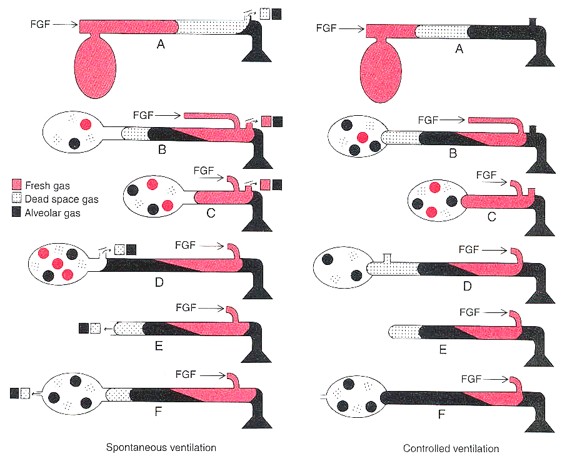
Controlled ventilation
During expiration:
- Pressure in the system will remain low.
- No gas will escape through the APL valve, unless the bag becomes distended.
- Both alveolar and dead space gas remain in corrugated tubing; alveolar gas being nearest to the patient as dead space gas is expired 1st.
During inspiration:
- Alveolar gas is inhaled by the patient.
- High pressure generated in the system during inspiration by squeezing the bag leads to leakage of large proportion of FGF through the APL valve.
- To prevent rebreathing: FGF must be atleast thrice the alveolar minute volume.
Physiology of Mapleson B and C
Since, the FGF inlet is near the patient end – during expiration, 1st part of expired gas, i.e. dead-space gas passes down the corrugated tubing, along with FGF and the tubing near patient end contains FGF and some alveolar gas.
As the valve is in patient end, a mixture of alveolar and fresh gas passes out via the APL valve.
During inspiration, a mixture of fresh gas and retained alveolar gas is breathed in.
- Unsuitable for both spontaneous and controlled ventilation.
- Requires FGF twice to thrice of minute volume to adequately flush alveolar gas within the circuit and prevent rebreathing.
- Obsolete system – not used now a days.
- Mapleson C circuit aka Westminster facepiece (no corrugated tube) can be made small and light and may be used for resuscitation or to transfer patients.
Physiology of Mapleson D
APL valve in use of Mapleson D
- Spontaneous venilation: Open (excess gases are vented out during expiration)
- Manually controlled ventilation: Partially closed (pressure rises during inspiration due to squeezing of bag and excess gases are vented out)
- Mechanically controlled ventilation: Closed (excess gases are vented through the ventilator spill valve).
Spontaneous ventilation
1. During expiration:
- Exhaled gas mix with FGF, move through the corrugate tube, towards the bag.
- When bag has filled, gas exits via APL valve.
2. During expiratory pause:
- As FGF inlet is near patient end, FGF pushes exhaled gas down the corrugated tubing.
3. During inspiration:
- The first gast to be inhaled is FGF from inlet and corrugated tubing. The contribution of this to the tidal volume will depend upon the FGF and the expiratory pause. During later part of inspiration the mixture of fresh gas, dead space gas and alveolar gas enters the patient. Some of these gases remain in the anatomical dead space of the patient, hence minimizing the effect of rebreathing.
- High FGF – all gases drawn from the corrugated tube will be FGF
- Low FGF – exhaled gas containing carbon dioxide will be inhaled
Controlled ventilation
The functional analysis is similar in both spontaneous and controlled ventilation. Hence this system can be used safely during both spontaneous and controlled ventilation. The system is slightly more efficient during controlled ventilation because of the control over the expiratory pause. When high FGF (> 2 times the minute volume) is used, there is no rebreathing and the minute ventilation determines the arterial CO2 levels.
Mapleson E and F physiology
Due to absence of APL valve, the resistance in the system is lower compared to other systems and are preferred in pediatric patients for both the spontaneous and controlled ventilation. In Mapleson F or Jackson Ree’s circuit APL valve are replaced with open ended reservoir bag. Functionally, they are similar to Mapleson D.
Factors playing role in Rebreathing
Higher the Free gas flow (FGF), more efficient is the flushing of alveolar gas.
Longer the expiratory pause, more FGF is available, decreasing the rebreathing.
Higher the tidal volume, higher the alveolar gas enter corrugated tubing, increasing the rebreathing.
Aid for Viva-voce and Summary
- Fresh gas flow (FGF) inlet near reservoir bag = Mapleson A
- FGF inlet and APL valve near face mask = Mapleson B
- No corrugated tubing = Mapleson C
- APL valve near reservoir bag =Mapleson D
- No APL valve and reservoir bag = Mapleson E
- Open ended reservoir bag but No APL valve = Mapleson F
- Efficiency in Spontaneous ventilation: A>DFE>CB (Mnemonic: A Dog Can’t Bite)
- Efficiency in Controlled ventilation: DFE>BC>A
- Mapleson D is effective for both the controlled and spontaneous ventilation.
- Mapleson C is used in recovery rooms because they are small and light weight (no corrugated tubing).
- Jackson Ree’s circuit is used for both the spontaneous and controlled ventilation in pediatric patients.